

Views: 0 Author: Site Editor Publish Time: 2026-07-15 Origin: Site


The transition zone between fixed land and dynamic water environments presents a strict engineering challenge. Structural failure at this juncture directly translates to liability, lost operational revenue, and restricted access. Marina operators and waterfront developers face compounding engineering challenges daily. They must accommodate extreme tidal shifts, ensure ADA compliance, and mitigate accelerated wear on transition hardware in highly corrosive marine environments. A poorly designed access point creates immediate bottlenecks and safety hazards for all users.
This technical evaluation guide provides a framework for selecting, sizing, and integrating floating systems and access bridges. By understanding the mechanical relationships between shoreline abutments and floating platforms, facility managers can ensure long-term structural integrity, operational efficiency, and user safety. We will examine load transfers, material selection, and specific hardware requirements needed to build a resilient waterfront access system.
System Interdependence: A floating dock is only as viable as its access point; gangways and marina pontoons must be engineered as a unified system to handle dynamic load transfers, wave action, and tidal fluctuations.
Material Lifecycle: Specifying an Aluminum Pontoon or gangway offers superior corrosion resistance and weight-to-strength ratios, significantly reducing long-term maintenance overhead compared to traditional timber or unprotected steel.
Strict ADA Compliance: Modern marina design requires precise gangway lengths, specific slope ratios (maximum 1:12), clear turning radiuses, and engineered transition plates to ensure equitable, unobstructed access.
Mitigating Mechanical Wear: The highest risk of structural failure occurs at the connection points—hinges, abutments, and rollers—requiring heavy-duty, purpose-built elastomeric and stainless-steel hardware for high-cycle environments.
The primary objective of waterfront access infrastructure is maintaining a stable, continuous path of travel regardless of water level, wake action, or live loads. Achieving this requires precise coordination between moving parts. The system functions as a three-part ecosystem: the fixed shoreline abutment, the articulating bridge, and the floating receiver. If any single component lacks the necessary load capacity, the entire access point becomes a liability.
Wind, wave action, and pedestrian traffic create multi-directional stress on connection points. These forces demand engineered tolerances rather than rigid fixtures. When a wave strikes the floating platform, the energy transfers directly up the access ramp to the shoreline. Without proper articulation, rigid joints will fracture under cyclical loading. Engineers must account for dead loads, live loads, and environmental loads simultaneously.
Basin layout and wave attenuation dynamics play a massive role in structural longevity. The orientation of the basin directly affects the structural load on the access ramp. Utilizing heavy-duty marina pontoons as integrated wave attenuators or breakwaters shields the primary landing from destructive lateral force. This strategic placement reduces fatigue on hinges and rollers. Proper basin design minimizes the fetch length, which directly limits the size of wind-generated waves hitting the access infrastructure.
To properly evaluate the structural relationship, site managers must assess the following dynamic load factors:
Pedestrian Live Loads: Standard requirements dictate supporting 100 pounds per square foot (psf) to accommodate crowded events or emergency evacuations.
Wind Uplift and Lateral Shear: Coastal installations must withstand hurricane-force winds, requiring specific tie-down mechanisms and heavy-duty hinge pins.
Torsional Stress: As boats wake hits the floating platform at an angle, the ramp twists. The connection hardware must allow for this rotation without binding.
Impact Loads: Accidental vessel strikes against the landing platform transfer massive shockwaves up the ramp, necessitating shock-absorbing abutment pads.
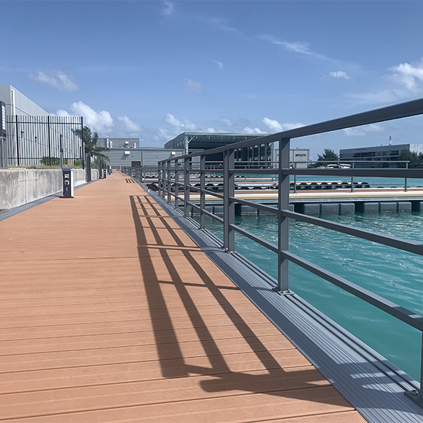
Traditional timber systems face severe operational limits in marine environments. Timber is highly vulnerable to marine borers, rot, splintering, and fasteners loosening under cyclical wave action. Wood absorbs water over time, changing its buoyancy profile and increasing the strain on anchoring systems. Treated lumber leaches chemicals into the water, drawing regulatory scrutiny in protected habitats.
While timber offers short-term initial savings, the operational lifespan dictates a different reality. The high frequency of structural inspections, frequent deck board replacements, and eventual float failure make timber a high-maintenance choice for commercial applications. Fastener pull-out remains a constant issue as the wood swells and contracts with moisture changes. Stringers warp, causing uneven deck surfaces that create tripping hazards.
Modern facilities increasingly rely on metal structures for their primary floating assets. Specifying an Aluminum Pontoon provides a high strength-to-weight ratio. This characteristic allows for greater buoyancy efficiency, heavier live-load capacities, and easier modular expansion. Aluminum frames resist twisting and warping, maintaining a perfectly level deck surface. The extrusion process allows for custom profiles that integrate utility channels directly into the frame.
Aluminum's natural oxidation layer prevents deep structural rust. This makes it ideal for saltwater and brackish environments. Unlike steel, which requires constant galvanization checks, aluminum maintains its structural integrity with minimal surface maintenance. Marine-grade alloys, specifically 6061-T6, offer exceptional yield strength while remaining lightweight enough for easy transport and installation. Welded joints in aluminum frames provide rigid, unyielding connections that outlast bolted timber frames by decades.
Concrete systems offer massive displacement and excellent wave-attenuation benefits. Their sheer mass dampens wake action effectively. However, they require specialized pile-anchoring and higher initial installation efforts. Concrete is prone to spalling if internal rebar corrodes. Micro-cracks allow saltwater to reach the steel reinforcement, causing it to expand and blow out chunks of concrete. This requires expensive epoxy injections to repair.
Lower-tier plastics or composites face UV degradation risks. While high-density polyethylene (HDPE) resists impact, it lacks the rigid spanning capabilities of aluminum or concrete, often requiring internal metal reinforcement. Unreinforced plastic floats can deform under heavy live loads or extreme heat, compromising the stability of the walking surface.
Material Type | Structural Yield Strength | Corrosion Resistance | Maintenance Frequency | Primary Application |
|---|---|---|---|---|
Treated Timber | Low to Moderate | Poor (Requires chemical treatment) | High (Annual fastener checks) | Sheltered residential docks |
6061-T6 Aluminum | High | Excellent (Natural oxidation) | Low (Visual weld inspections) | Commercial marinas, high-traffic access |
Reinforced Concrete | Very High | Moderate (Risk of rebar spalling) | Moderate (Crack sealing) | Exposed coastal breakwaters |
HDPE Composite | Low (Requires metal core) | Excellent | Low | Small inland lakes, temporary access |
The mathematical relationship between tidal range and ramp length dictates user safety. A Gangway bridge must be long enough to prevent exceeding maximum slope angles during low tide. Short ramps create impossibly steep inclines during negative tides. If the slope exceeds safe limits, mobility devices lose traction, and pedestrians risk severe falls.
Conducting a site-specific bathymetric and tidal survey is mandatory. Engineers use the lowest astronomical tide (LAT) and the highest astronomical tide (HAT) to determine the minimum required length. The goal is to keep the slope manageable even at the lowest water mark. You must calculate the vertical drop from the fixed abutment hinge to the floating deck at LAT. Using trigonometry, you determine the hypotenuse required to maintain a slope no steeper than 1:12.
Massive tidal swings present a difficult engineering problem. In areas with 20-foot tidal shifts, a single standard ramp would require an impractical, excessive length, sometimes exceeding 150 feet. This creates unmanageable structural deflection. A single span of that length acts like a sail in high winds and requires massive, expensive trusses to prevent sagging in the middle.
Engineers solve this using telescoping systems or multi-stage articulated platforms. These configurations use intermediate floating landings to break up extreme vertical transitions. This approach keeps individual ramp sections manageable and maintains safe slope angles throughout the tidal cycle. Multi-stage systems utilize a series of switchbacks supported by intermediate pilings and floating platforms, significantly reducing the footprint required on the shoreline.
Rollers and hinges represent the primary points of mechanical failure. Constant motion grinds down standard hardware rapidly. Binding rollers cause the ramp to push the floating platform out of alignment. When rollers seize, the bottom of the ramp acts like a plow, gouging the deck of the floating platform and transferring massive shear force back to the shoreline abutment.
Mitigation requires specific hardware solutions. UHMW (Ultra-High Molecular Weight) polyethylene rollers provide silent, frictionless movement. Marine-grade stainless steel hinge pins resist shearing forces. Self-adjusting transition plates prevent binding, structural fatigue, and noise while providing a smooth walking surface. Transition plates must feature a beveled edge to prevent tripping and should be coated with a non-slip aggregate.
Key hardware specifications for high-cycle environments include:
Abutment Hinges: Minimum 1-inch diameter 316L stainless steel pins with greaseable bronze bushings.
Roller Assemblies: Dual-wheel UHMW rollers mounted on a solid stainless steel axle, running on a reinforced aluminum track plate.
Transition Plates: 1/4-inch aluminum diamond plate with a piano hinge connection to the ramp frame.
Fasteners: Nylon-insert lock nuts on all moving assemblies to prevent vibration-induced loosening.
The Americans with Disabilities Act (ADA) provides strict guidelines for marinas. The core rule mandates a 1:12 maximum slope ratio. Ramps exceeding specific lengths require level resting platforms to prevent user fatigue. These resting platforms must be completely level and provide enough space for a wheelchair to stop safely without rolling backward.
Technical exceptions exist for extreme low-water events, but facilities must document compliance meticulously. Where the ramp landing meets the floating platform, turning radius specifications dictate a minimum clear space. This prevents wheelchair entrapment and allows users to safely navigate the 90-degree turn onto the main dock. The landing area must provide a minimum 60-inch by 60-inch clear space to accommodate a full 360-degree turn for mobility devices.
Continuous, graspable handrails are non-negotiable. Edge protection, typically in the form of kick plates, prevents mobility devices from slipping off the edge. These barriers must run the entire length of the span. Handrails must be positioned at exactly 34 to 38 inches above the walking surface and extend beyond the top and bottom of the ramp run.
Decking materials must provide maximum traction in wet conditions while allowing water and debris to pass through. Micro-mesh fiberglass grating and grooved aluminum are superior choices. They prevent standing water and offer aggressive slip resistance without impeding wheelchair casters. Wood decking, even when grooved, becomes slick with algae and requires constant pressure washing to maintain safe traction levels.
Routing utilities across a moving joint requires careful planning. Freshwater lines, electrical conduits, and fueling lines must integrate directly along the structure without disrupting the pedestrian path. Flexible utility loops accommodate the vertical travel without rupturing. These loops must be sized to handle the maximum extension at low tide and the maximum compression at high tide without kinking.
Safety amenities enhance the overall user experience. Structural integration of emergency boarding gates, high-visibility LED lighting, and safety ladders on the perimeter ensures rapid response capabilities during accidental water entries. Lighting should be mounted low on the handrail posts to illuminate the deck surface without blinding boaters navigating the basin at night.
The fixed shoreline abutment anchors the entire system. It must withstand massive pull-out forces generated by the floating system during storm surges. Deep concrete footings and engineered seawall tie-backs are standard requirements. The abutment must be poured behind the seawall to prevent undermining from tidal erosion. Engineers calculate the deadman anchor size based on the maximum lateral load transferred through the ramp during a storm event.
Anchoring the floating sections depends on seabed composition and current velocity. Pile-guided systems offer excellent vertical travel but require deep mud. Chain-and-block anchoring or stiff-arms provide alternatives for rocky seabeds or deep-water installations. Helical anchors drilled into the seabed offer superior holding power in loose sand, connecting to the floating platform via heavy-duty elastic rodes that absorb shock loads.
Transition points between individual floating modules endure constant torsional strain. Rigid bolting will fracture under wave action. Flexible, elastomeric shock-absorbing connectors handle this strain effectively. They allow the dock to undulate with the water while maintaining structural unity. These connectors utilize heavy rubber blocks compressed between steel plates, absorbing the kinetic energy of the waves before it can tear the frame apart.
Mixing dissimilar metals in a wet environment triggers galvanic corrosion. The less noble metal sacrifices itself rapidly. Isolating components using dielectric pads or sacrificial anodes is essential for longevity. Never bolt stainless steel directly to aluminum without a barrier. Use nylon washers, Tef-Gel, or micarta plates to break the electrical connection between the metals.
A realistic annual maintenance checklist keeps operations running smoothly. Facility managers must inspect welds, verify torque specifications on all bolts, clear roller tracks of debris, and pressure-test utility connections before peak season. Neglecting these basic checks leads to catastrophic failures during storm events.
Initiate a comprehensive site survey, including precise bathymetric mapping and tidal range data collection, to determine exact slope requirements.
Consult a licensed marine structural engineer to calculate dynamic load transfers and specify appropriate shoreline abutment footings.
Demand stamped engineering drawings and verifiable load calculations from manufacturers rather than purchasing off-the-shelf components.
Implement a strict, documented annual inspection schedule focusing on hinges, rollers, and galvanic corrosion indicators.
A: The ADA standard mandates a maximum slope of 1:12 (8.33%). Exceptions exist for extreme tidal fluctuations, but resting platforms are required for ramps exceeding specific continuous lengths.
A: Length is calculated using the lowest astronomical tide (LAT) and the required maximum slope angle. The formula ensures the ramp remains at or below a 1:12 slope during the lowest expected water levels.
A: Aluminum offers superior corrosion resistance, eliminates rot and splintering, requires lower maintenance, provides consistent buoyancy, and easily integrates utility chases without compromising structural integrity.
A: Transition plates bridge the gap between the moving ramp and the floating platform. They create a smooth, continuous surface, preventing tripping hazards and wheelchair entrapment during tidal shifts.
A: Utilities are routed using flexible loops and expansion joints. They are secured in dedicated channels beneath or alongside the structure to prevent line rupture and keep the pedestrian path clear.
A: Engineers use UHMW polyethylene rollers at the landing point. These rollers glide on protective metal track plates installed on the deck, distributing the weight and preventing gouging or friction damage.